Mark Schimmer
Mark Schimmer
Gameport Rudders
Says Mark Schimmer:
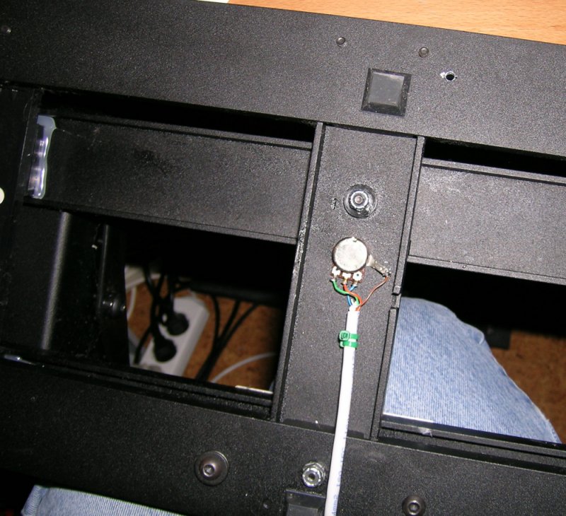
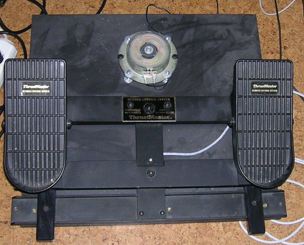
Ever since I replaced my Saitek X36 with the X45 model I had problems with my game-port Thrustmaster Elite rudder pedals. I did not want to replace them, for they function well enough. My first idea was to take the throttle-unit apart and trace the cables to the potentiometer, which is actuated by the rocker on the underside of the throttle grip (by any means, avoid taking that throttle apart. It is a horrible mess to put together again).
While tracing the cables from the potentiometer to the PCB and the outside connectors in the throttle, I found that the throttle-rudder signal continues on a normal analog wiring into the main stick unit. That was the solution! Intercept the wires in a self-made ""dongle"" without modifying anything on the stick! The idea was to intercept the signal-lines and replace them with the ones leading to the TM Rudder.
My first setup didn't work, because the TM is wired as a simple resistance measuring potentiometer, as demanded by the game port. Saitek went all the way with the design (good descision!) and used a classical voltage divider, which is superior to the simple resistance solution. The voltage divider uses 5 Volts and ground on the outer potentiometer terminals, and the signal is on the slider in the middle. So I had to re-wire the TM Rudder for that, which was no problem, since the already built-in pot is of the right kind. Just replace the cable and keep it somewhere, if some day one has to return to the original configuration.
What to do:
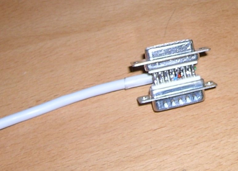
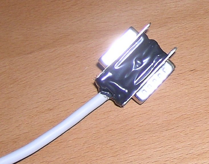
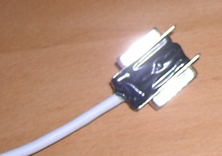
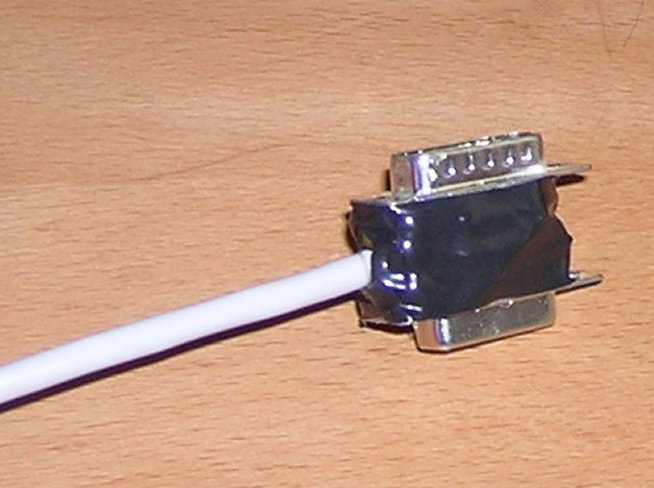
Take a male and a female game-port connector. Have a look at the back of the connectors, where the soldering terminals sit. Here you see small numbers: these are the pin numbers. Take a fine cutter or whatever and remove the terminals 13 and 5 completly off the MALE connector (this will be the one facing the throttle unit). Now solder these two connectors directly back to back together. On the female side, solder the wire of the TM rudder slider (middle) potentiometer terminal to pin 13. Viewing the potentiometer from above on the back side, you see the middle terminal on six o'clock. Take the starboard, er, right terminal wire and solder it to pin 8. Take the left terminal wire and solder it to pin 5. That's it!
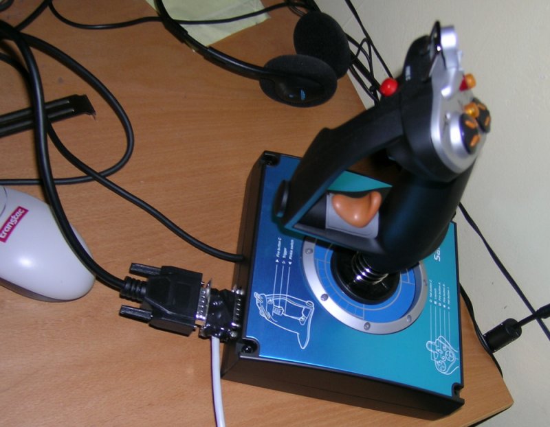
Plug it in. P-o-o-o-f! Hehe, just joking.
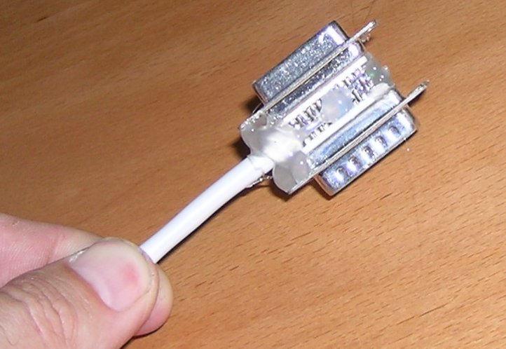
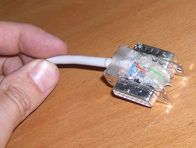
Now check the function. If you find that the rudder is reversed, reverse the wires running to terminal 8 and 5. Do not work around by reversing the channels by software, since not all sims support such a function. I applied a good dose of heat glue on the dongle to secure the wiring and wrapped some insulation tape around it, and it worked right away. Mechanically, it is incredibly strong. You just have to watch that the rudder-cable sits firm and secure.
Here's the schematic:
Rudder-Pot Dongle-Connector Action on terminals Action soldering
_______
| |--------------- 8 (5 Volts) don't cut these Terminals! Solder
| |--------------- 13 Signal cut on male side Solder to female side
| |--------------- 5 Ground cut on male side Solder to female side
|______|
I'm sure this works with other game-port style rudders, too.
The following Model of the stick, the X52, has no more rocker on the throttle unit, unfortunatly. Instead Saitek implemented a twist grip (not my favorite) in the main unit. Hint: first thing I'd try if I had one of these would be to route the wires of the twist grip pot to my elite pedals. If it still has a pot, of course.....
Have fun!
Mark Schimmer